1. Crude Atmospheric Distillation:
The Crude Unit being the only one processing the entire amount of feed in the Refinery, requires special attention with regards to reliability.
By capital cost reasons there is a definite trend to install very large capacity furnaces, sometimes even only one for the complete Refinery, therefore there is no typical size or typology for such kind of furnaces.
Based on best compromise of operability, reliability and investment cost the selection of the crude heaters for new installation is recommended as follows:
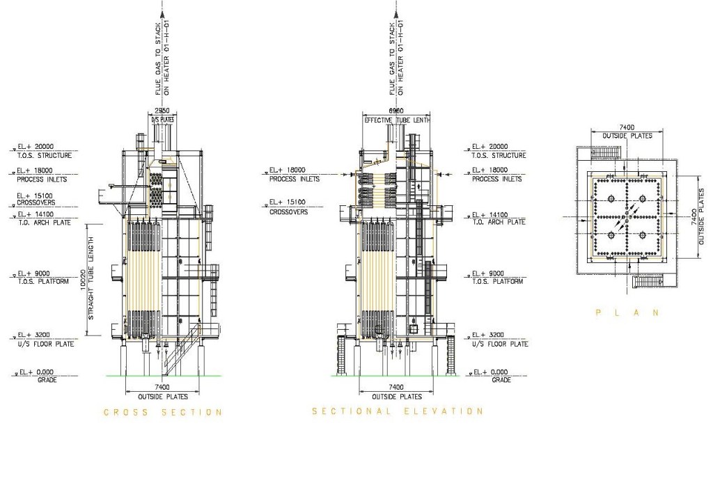
○ Up to 40 Million kCal/hr thermal capacity the vertical cylindrical type of heaters is preferred. This generally allows good plot arrangement, low cost and reduced number of burners.
○From 40 to 150 or more Million kCal/hr thermal capacity the so called “High Intensity” type will allow most compact design and minimal number of burners at the minimum capital cost.
The “High Intensity” heaters feature vertical tubes in a box envelope with tubes being fired partly from one and partly from both sides. Very large capacity forced draft burners are installed in the floor of the furnace working at low excess air.
In connection with large capacity, a high efficiency (in the range of 88 to 90%) is always required and reached via different arrangement of the waste heat recovery unit on the flue gases such as:
○ Direct air preheaters when there are no particular concerns about acid flue gas condensation.
○ Direct air preheaters with steam-air attemperator on the cold air inlet to prevent low temperature corrosion.
○ Indirect air preheaters where an intermediate fluid (thermal oil or similar) is heated in the convection section and then pumped around in close circuit to heat up the combustion air. This system is the preferable to avoid any risk of acid flue gas condensation.
○ Steam raising in waste heat boilers only when steam production is valuable in the overall refinery balance.
Special attention in the design of crude distillation heaters goes to process control, which is using the benefit of DCS optimization which allows to implement all the algorithms to keep a smooth run of the furnace independently of the feed flow variation as well as of the fuel composition fluctuation.
2. Vacuum Distillation Heater:
Modern refineries are based on maximisation of conversion and require vacuum distillation operation to fit with the flow diagram of the overall process. This means that the vacuum tower operation must be steady without impacts coming from fired heater fluctuation.
The design has to guarantee that the profiles of pressure, temperature and vaporisation from the inlet to the heater to the tower will be achieved during operation independently of feed variation and fuel fluctuation. Fluid-dynamic simulation of the outlet tubes, manifold and transfer line are to be carried out to have the highest possible symmetry of the different flow streams resulting in equal individual flows properties.
A similar DCS control as described for the crude distillation unit is suitable for vacuum distillation as well and is necessary to keep on the long run the above conditions.
Considering the layout of the furnace, capital cost consideration are the same as for crude distillation with smaller heaters being designed as vertical cylindrical and larger one being done to the “high intensity concept”.
Vertical tube heaters will be distributed in the minimum number of streams suitable for the allowable pressure drop even if resulting in large outlet tube diameter. In our experience such tubes, in order to stay safely below the critical velocity, may have diameter as large as 350 mm.
3. Catalytic Reforming:
The main characteristic of fired heaters for catalytic reforming unit is the very high gas feed flows that need to be heated and then reheated several times for the different adiabatic reaction steps.
This implies very large compressors being used to give the system the necessary flowrate. Operating as well as capital cost consideration are, therefore, in favour of low pressure drop multi-pass heater design.
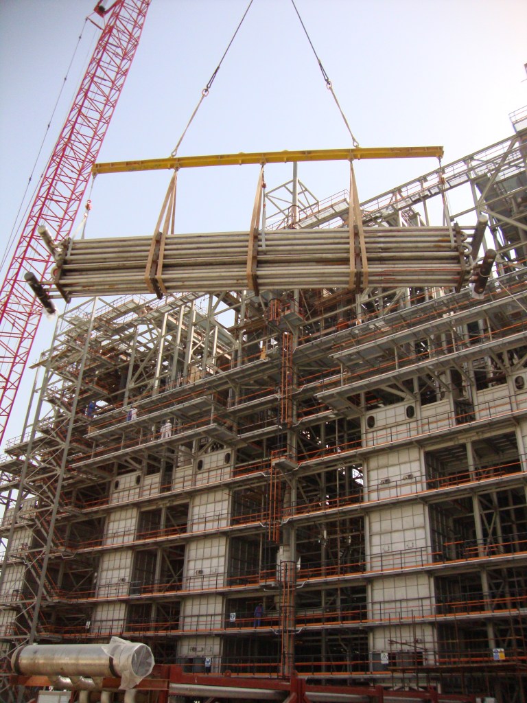
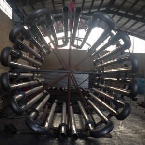
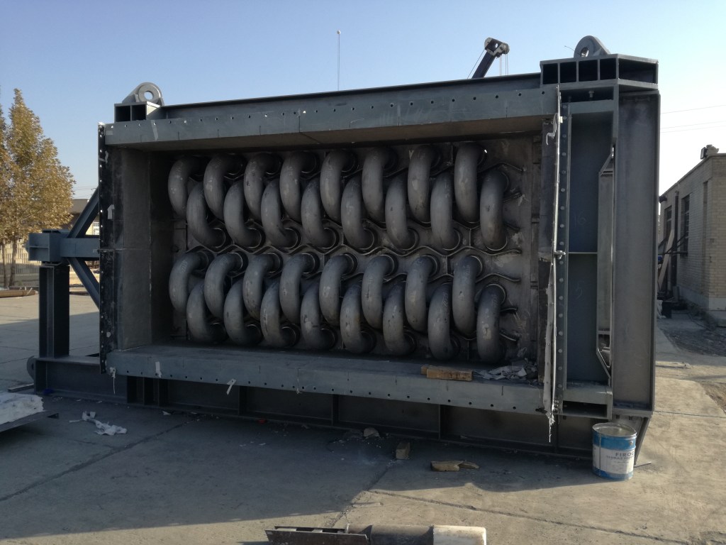
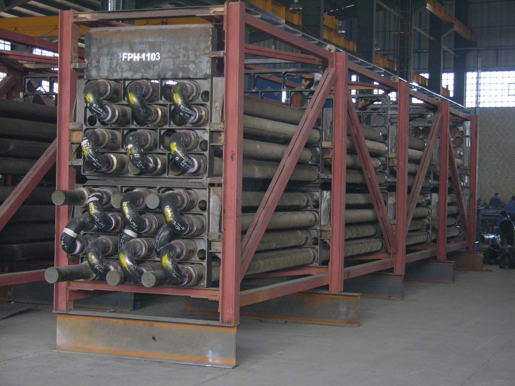
The use of parallel inlet/outlet manifold and low pressure drop tubes hairpins having very large radius return bends located in the firebox is the most common solution. In order to further minimise the coil tube length, the double fired arrangement is preferred when high duties are involved even though other consideration may time to time suggest different solutions.
Manifolds may be top (fig.5) or bottom installed, with the last option being preferred in our experience since the load of the radiant coil may be taken by the concrete foundation instead of needing unnecessary additional structure in the radiant steelwork envelope.
Due to the very tight layout of the multistage reactors special experience is needed in the design of the manifold expansion which has to be fully taken inside the radiant box by the movements of the radiant coil. A complex system of spring supports and guides has to be studied to achieve this result.
Modern heaters are based on low pressure drop design therefore can not accept the high pressure drop of conventional tube bundle convection coil. As a consequence, the process service in the heaters is segregated in the radiant section and has very low thermal efficiency with flue gas leaving radiant section typically around 800°C. Since the catalytic reformers size is in general very large, it is imperative to recover the waste heat up to an overall efficiency of around 90% with or without air preheating. This means that the raising steam is an unavoidable solution but it is still possible to use part or all of the waste heat to preheat the charge to the different re-boiling columns connected to the unit (splitter, debutanizer etc.) bearing in mind the heat transfer optimization concept of pinch technology as well as the needs of flexibility in start up and operation.
4. Steam Reforming for Hydrogen manufacturing:
Among the various kind of fired heaters in refinery service, the steam reforming furnaces are the ones that have been subject to more improvements in the past years. These improvements were achieved in the areas of major concern:
○ Tube metallurgy
○ Catalyst
○ Coil configuration and firing arrangement
○ Inlet and outlet headers system
Tube metallurgy improved to the latest generation HP 35 Modified Microalloys grade (25 Ni 35 Cr + Nb + micro quantities of special elements). The implementation of such new materials has led to much thinner tube thickness at same design conditions (typically 9 mm).
At same time the new generation of catalysts developed by the leading catalyst manufacturers has allowed to design at higher heat flux still avoiding carbon formation and or catalyst damages (typically 70.000 – 80.000 kCal/m2 hr).
The coil arrangement has evolved from the old side fired layout to the most modern top fired one where vertical lanes of tubes fed from the top are fired on both sides by burners installed in the arch of the furnace. This layout allows:
○ Modularity of size: more lanes of tubes may be added in one single radiant box up to Hydrogen production of 150.000+ Nm3/hr.
○ Optimized heat flux: the major part of the heat is given where required, i.e. at the top cold section of the tubes
○ Optimized use of tube material: due to the fairly flat tube skin temperature profile the minimum required thickness is almost the same in each section along the tube length.
Very important improvements have been achieved also in the field of mechanical design of the outlet headers where, in order to avoid any mechanical stress to the catalyst tube, long flexible tubing is used to connect the inlet and the outlet headers to each of the individual catalyst tubes. The load of the tubes, therefore, is easily taken by the floor of the furnaces and by the top spring supports with no movement other than vertical expansion and no external load other than the dead weight of the catalyst tube themselves.
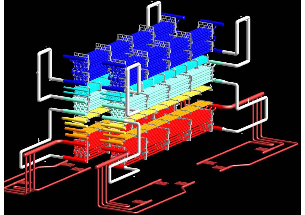
The high temperatures involved in the process of steam reforming result in very high temperature of the flue gases leaving the radiant section. Several solutions are available to recover the heat from such gases:
○ Hydrocarbon feed preheating
○ Hydrocarbon/steam mixed flow preheating
○ Boiler feed water preheating
○ Steam generation
○ Steam superheating
○ Combustion air preheating
Depending on the economic value given to steam production in the overall refinery balance, such production may be maximized or limited to the steam flow required for the steam reforming reaction only. The unit will then be either a net steam exporter or a self sufficient steam producer. In any case the approach of the pinch technology has to be followed in order to have the best utilization of the heat source at the various temperatures. which in turn will allow to optimize the selection of metallurgy for the tubes of the different streams.

5. Visbreaking:
Fired heaters in Visbreaking service (as well as in any cracking application) are to be considered as reactor furnaces and their design needs all necessary knowledge of cracking kinetics in general and Visbreaking process specifically.
Based on the feed composition and the coil geometry, Manmont takes the advantage of simulation programs which enables designers to predict the conversion rate and product composition at different temperature / pressure / heat flux conditions. The model will also predict the tube skin and film temperature profiles allowing to avoid film overheating and keeping control on the formation of undesired by-products (like the asphaltenes) that may have negative impact on the stabilization of the fuel oil produced in the Visbreaking unit.
The program takes also into account both liquid phase and vapour phase reactions and contains a model for the prediction of coke build up at a given forecast of running conditions.
As far as heater coil geometry is concerned, the simulation program shows no particular need for any specific lay out, therefore the most economical arrangement may be preferred, like the vertical cylindrical one.
6. Cracking Furnace:
The cracking furnace is the heart of the cracker which defines the capacity and profitability of the cracker for Ethylene and/or Propylene production. Normally, there are two types of cracking furnaces which are designed to crack the gaseous and liquid feedstock separately.
Our designers have continuously been working in the direction of optimization and safe operation of the cracking furnace. The feed to furnace enters the feed pre heater bundle to increase its temperature before mixing with dilution steam. The tube metal temperature as well as insulation around must be designed in such a manner that any risk of flue gas condensation can be avoided. Moreover, the roof of the furnace shall be at minimum distance from bundle which we will take care during detail design. Moreover, any eddy formation shall also be avoided to avoid extra pressure drop.
In case of liquid, furnace feed preheater bundle not only increases the process temperature but also vaporizes the feedstock above 50%. The temperature at outlet of pre-heater is designed in such a manner that there is no risk of condensation on the mixing of the dilution steam. The complete vaporization of liquid feed takes place in the mixing nozzle at a temperature which is far from its dew point of hydrocarbon and steam mixture. We will take care of mixing nozzle design so that we will have sufficient distance to dew point and no mist flow at end of the nozzle. Nozzle installation and length have to be checked during the detailed engineering for process as well as mechanical aspect. Hence, any risk of erosion in low temperature convection bundle (HTC-1) can be avoided.
After mixing steam with feed to lower the hydrocarbon partial pressure, the mixture is superheated in HTC-1 and HTC-2 bundles before it enters crossover header for the distribution of feed and steam mixture to the split coils. Crossover is a manifold which is connected to each of coil inlets via venturi nozzle to feed them with hydrocarbon and steam mixture at constant temperature and pressure. The pressure drop in the cross over header is optimized in such a manner that each pass will have equal flow through the venturi nozzles. Installation and design of the crossover shall be very precise as it holds the pigtails on it which connects to the radiant coils. Due to thermal expansion, the designs of crossovers as well as associated support need to be investigated in very much in details. The faulty design of crossover might lead to improper distribution of feed through the header and in the worst cases cracks on pigtail joint which may lead to explosive environment.
For the furnace designed for liquid cracking, the dilution steam is superheated in dilution steam super heater prior to the mixing with hydrocarbons so that it helps in complete vaporization of the naphtha feedstock.
In the radiant coils (placed in the radiant boxes), the cracking occurs to produces olefins and byproducts. Due to optimized heat flux via floor and wall burners, the whole coil length experiences a uniform heat from outside so that temperature gradient will be similar for all the coils. The combination of floor and wall firing provides excellent radiant section efficiency and good heat distribution. The coils have no fixed support as whole system hangs on the hangers without any bend fixed on the furnace floor. The hanging system helps the coil to relax in the high thermal conditions.
Each of the radiant boxes consists of floor and side wall burners, 70 – 75 percent of the total required fired duty is given by the floor burners and 30 -25 percent of total required fired duty is given by wall burners. A combination of wall with floor firing makes the fuel gas piping arrangement complex. The performance of the burners is very much dependent on the available pressure at inlet. The fuel gas piping arrangement shall take care of maximum allowable pressure drop so that furnace shall not experience any bottleneck due to lack of fuel gas pressure at burner.
Cracking is an endothermic reaction which requires heat for chemical reactions. The heat is given to the coils via floor and wall burners. The typical efficiency of firebox i.e. heat transferred to the cracking reaction, is in the vicinity of 42-45% which means that rest of the heat flows to the convection section for heat recovery.
Cracked gas at high temperature comes out of the radiant coil and passes through the quench system so that temperature of the hydrocarbons goes down and further cracking is frozen. In inlet section of the quench exchanger is most critical part in whole assembly since it experiences huge temperature difference between cold side i.e. boiler feed water and hot side i.e. cracked gas. The thermal stress analysis is performed to determine the suitability of the material for the given process conditions. The routing of riser and downcomer lines have to be designed to minimize pressure drop for natural circulation. After quenching in the quench exchanger, the cracked gas is routed to quench fitting in furnace Type II for further cooling.
The quench system receives BFW from the steam drum which is located at top of the furnaces. The BFW to the steam drum comes from the convection section after preheating in economizer bundles. The heat from the cracked gas is utilized to generate saturated high-pressure steam in quench exchangers. For the liquid furnaces, the cracked gas after first stage of quenching is routed to the quench fitting. The quench fitting reduces cracked gas temperature by direct injection of quench oil. The mixing and rapid cooling of cracked gas is achieved in specially designed injection device.
The boiler feed water (BFW) is preheated in the convection section prior to entering the steam drum. The steam drum provides saturated BFW to the quench exchangers to reduce cracked gas temperature below required cracking temperature while generating saturated high-pressure steam. The quench system operates on the natural circulation. The saturated steam is fed back to steam drum which provides saturated steam to superheater bundles in the convection section for the steam superheating.
Superheater bundles are split so that an intermediate boiler feed water injection to control the temperature of superheater steam can be installed. The split coil provides an excellent run length for liquid/gas feedstock.
7. Coking:
All considerations about the need for a rigorous kinetics modelling program, Visbreaking unit, are in general valid also for the Coking unit heaters as well. However, the higher criticality of Coking versus Visbreaking reaction result in some specific differences:
○ Faster coke build-up means shorter run time and requires more than one heater (typically two) to be installed in the unit. This allows to run at reduced capacity during the decoking operation.
○ Much lower residence time / higher mass velocity is required to have the smallest possible difference between bulk and film temperature, thus allowing for the required conversion rate at minimal coke build-up on the inner tube surface.
Simulation software and field feedback data show that the preferable configuration is the horizontal tube lay out with two heaters running in parallel.
8. Hydrocracking:
Selection of heaters for the Hydrocracking units is strongly impacted by two main factors:
○ Relatively high process outlet temperature
○ Very high process pressure (typically 200 bars)
These two constraints result in the need for very thick high alloy tubes making the coil lay out the major factor in the competitive design of the heaters. To cope with the above, state of the art technology is to use the double fired tubes / vertical box heater featuring stainless steel coil material (typically ASTM grade 321H or 347H).
The double fired arrangement, where tubes are fired from both sides at minimal heat flux misdistribution and the optimized tube diameter selection allow keeping the tube thickness of such high alloy material within the range of commercially available coil material. Since no other specific process need is limiting the design, the most economical vertical tubes arrangement is selected.
